Table Tennis Ball Launcher
March 2025 – November 2025
Design and manufacture of a table tennis ball launcher powered by a DC motor. Part of Year 1 and 2 coursework.
The Brief
As part of our Design, Materials & Manufacturing module, we were tasked with designing and manufacturing a portable table tennis ball launcher from scratch. Positioned at a fixed point on the table, the launcher had to fire three balls to hit three zones on the opposite side: right, middle, and left (as shown below).
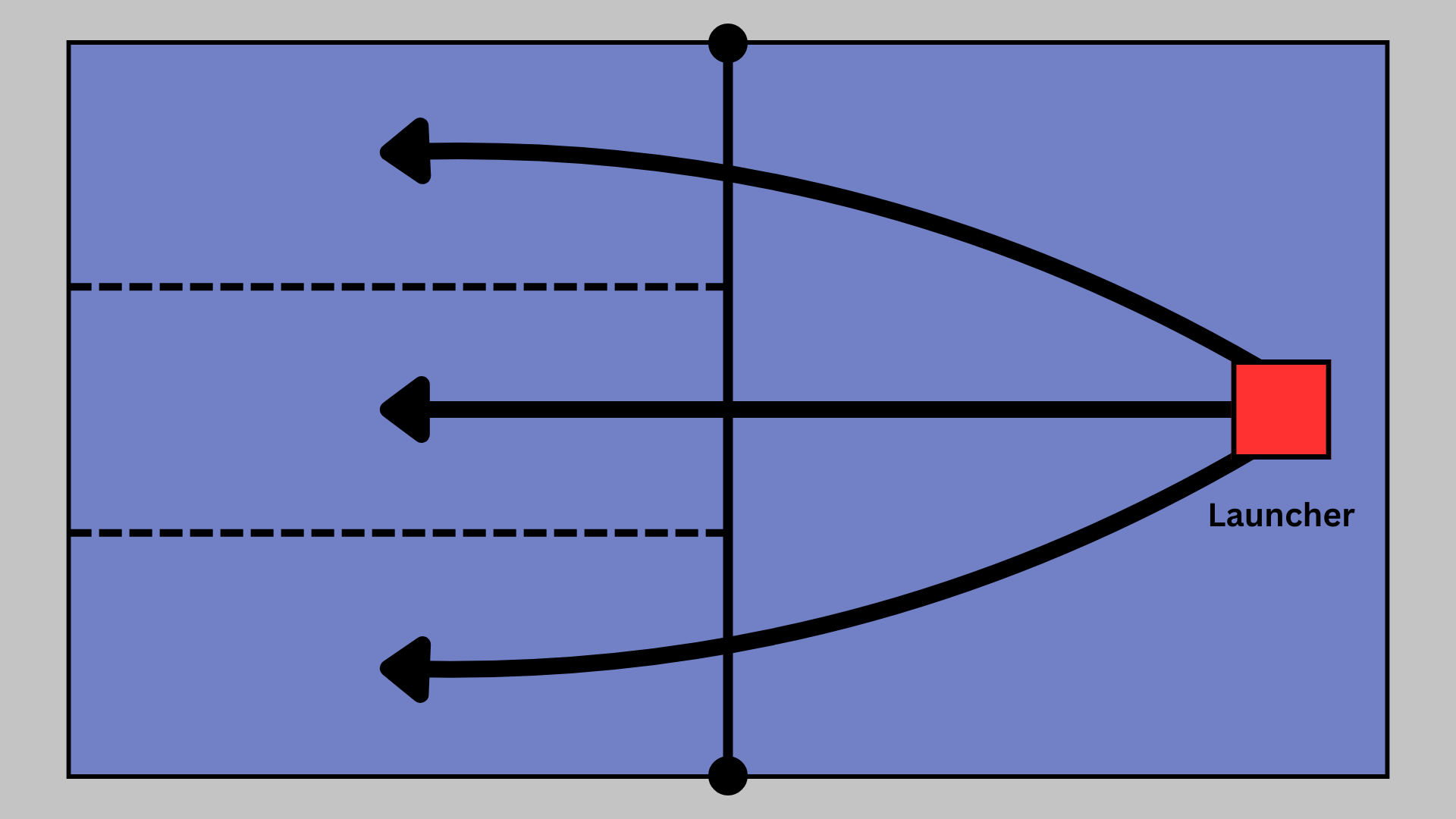 A diagram showing the 3 target zones for the launcher to hit.
We were given an external parts budget of £85 and could use up to two 9 V DC motors to power our machine. The most challenging constraint, however, was that the launcher had to operate using purely mechanical controls, meaning no microcontrollers were allowed.
My Role
In a team of five, I contributed heavily to the design stage, focusing on the aiming mechanism. My responsibilities included producing the detailed CAD for this subsystem, generating several part drawings, and preparing the final assembly drawing. This work developed my skills in mechanical design, technical drawing, and CAD modelling, while also requiring close collaboration with my teammate’s work on the timing and firing systems.
Our Design
After finalising the CAD model, we submitted our part drawings and order forms to the workshop technicians, who would manufacture or source the components over the summer. With only one build session when we returned in Year 2, the design needed to be both precise and resilient to common assembly issues.
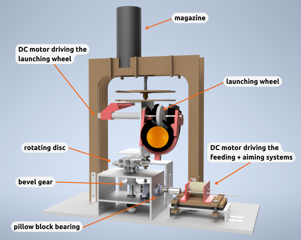 CAD render of our tennis ball launcher.
I designed the aiming mechanism with flexibility in mind:
- Rather than designing a gearbox from scratch, I opted for a modular DC motor gearbox kit, which would allow us to try different gear ratios to speed up or slow down the aiming motion as required.
- Pillow block bearings were chosen to reduce the effects brought on by shaft misalignment.
- The gearbox sits on a U-channel with thin rubber sheets beneath, allowing the motor height to be adjusted if the shafts don’t line up perfectly at the coupling.
- A pin on the rotating disc of the swivel mechanism can be positioned in three radial locations, adjusting the angle sweep.
These decisions made the aiming system more robust and adaptable, reducing the likelihood of build-stage setbacks and improving our chances of a successful first-time assembly.
The Result
The aiming mechanism performed as intended — the modular gearbox kit allowed us to change the sweep speed, and the adjustable pin on the acrylic turntable provided control over the sweep angle. However, the ball launching subsystem encountered issues during assembly: the rubber wheel failed to make contact with the ball, and our last-minute substitution of a rotating striker (laser-cut MDF) introduced significant vibrations to the machine. While the launcher did not achieve full accuracy across all three zones, the project delivered valuable lessons in mechanical design and manufacturing.
Future improvements could include more precise shaft positioning to prevent occasional lock-ups in the bevel gear meshing, and earlier physical prototyping of the main subsystems would have been useful. Overall, this project showed us the importance of designing for assembly tolerances and real-world constraints, with the adaptable aiming mechanism proving the value of designing for real-world assembly conditions from the outset.
See a short video of our launcher here:
![]()